Vox AC15CC Mod Guide
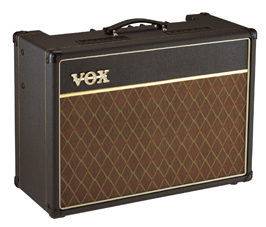
The Vox AC15CC, or AC15 Custom Classic is a nice amplifier – despite being manufactured in China, it has plenty of character and tone. Still, there are plenty of people on the internet willing to invest time into performing modifications on this amp to take it a step further. Having done quite a few modifications myself, I thought I would write an article to try and consolidate those that I have performed, both to document my journey and also to produce an easy access guide, so that you don’t have to scour the net looking for resources.
Disclaimer:
Operating voltages of valve amps are lethal and can remain lethal, even after the amp has been turned off. There is a serious risk of electrocution and possible death when working on valve amps.
The author of this article and GuitarPug.com will not be held responsible for any damage to gear, or injury to persons, as a result of reading this guide.
If you are uncertain in anyway, have the work done by an amp tech.
Additionally, please note that performing any any of these modifications will, in all likeliness, invalidate the manufacturer’s warranty.
Primer
If this is the first modification project you’ve embarked on, or you haven’t already read our guide on Must Have Tools For Modding and B.Y.O Kits, I suggest stopping by there as a first port of call.
Before you start any work on any valve amp, you MUST first check the voltages across the filter caps and discharge them if necessary. These filter caps are capable of storing up to 400 volts, even after the amp is turned off.
Another point, DO NOT power your amp up without a speaker load connected, you risk damaging your amplifier.
It is also wise to print out a schematic of the amp you are working on and document any changes you have made. That way, if you do need to take the amp to an amp tech, you can give them a schematic that correctly reflects the circuit. The schematic for the AC15CC is provided below.
Chassis Removal
The first step before working on your amp, is getting the chassis out. This is not hard and is worth attempting, even if you aren’t planning on modding your amp, as it gives easy access to the tubes for changes and other projects.
First, remove the back panel. Remove the six screws on the back panel, the panel should then slide off. These screws are phillips head #2 size.
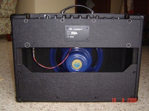
While you are at the back, disconnect the speaker from the chassis. If you are planning on fully removing the chassis to work on it, remove the reverb tank from the black pouch at the bottom of the cabinet. Remove the two crews on the left hand side, and the reverb tank will slip out. If you are just changing tubes, then removing the reverb tank is not required, as there is plenty of slack in the cable to place the chassis on the floor.
Next, on each side of the cabinet is two screws (phillips head #3). Remove the 4 screws in total. These are the screws that hold the chassis to the cabinet. Don’t worry about the chassis falling when you remove the screws, as it sits on wooden rails. The chassis will then slide out. It is normal if you have to use a bit of force to slide it out. The chassis also has a bit of weight in it, so be prepared as you are sliding it out.
Replacing Valves
This is extremely easy, straightforward to do and well worth the effort of learning to do it yourself. Knowing how to change your valves will save you money, instead of having to take it to an amp tech (unless of course, you suspect something else is wrong with the amp). The AC15CC has four valves; 2 x 12AX7 preamp tubes and 2 x EL84 power tubes. The valves are labeled V1, V2, V3 and V4. When looking at the back of the amp:
- V1 is the Top Boost channel valve – Furthest valve on the left, next to the output transformer.
- V2 is the phase inverter – Valve sitting to the immediate right of V1.
- V3 and V4 are the two power valves – The two valves sitting next to the power transformer, on the right hand side of the chassis.
V1 and V2 can be changed easily without removing the chassis, as you can reach around and access them. The tube protectors on V1 and V2 are spring loaded, just push down slightly and they’ll twist off. V3 and V4 are protected by a heat shield, which needs to be removed first. It is easiest to remove the chassis when replacing these valves, as the heat shield is screwed into the chassis.
As the AC15CC is a cathode biased amp, it does not require the bias to be set every time you change valves. As long as you purchase a matched pair of EL84 valves, you can whack them in and rock away! The 12AX7’s don’t have to be matched or anything, although some people like using a 12AX7 with balanced halves for V2, the phase inverter. Feel free to experiment with different valves to find your tone.

Speakers
The speaker in your amp has a massive influence on your tone. So if you are tone hunting, it’s worth considering a speaker upgrade. The AC15CC comes with two speaker choices; the Wharfedale or the Celestion Alnico Blue. The Celestion Alnico Blue is the better sounding speaker of the two. Not that the Wharfedale sounds bad, it just doesn’t sound like how a Vox should. Of course, that is a very subjective statement, but most people are chasing that vintage Vox tone that the Alnico Blue produces.
A good idea is trying to pick up an AC15CC with a Wharfedale speaker second hand, which will then enable you to experiment with different speakers. Apart from the Celestion Alnico Blue, the Webber Blue Dog is also a good choice.
Remember that new speakers need time to break in. So if your amp is new, give the speaker time to break in before you make any decisions about upgrading.
Accessing the PCB Board
With the amp lying face down on the floor, or the chassis removed, look inside. If you have removed the chassis, have the chassis sitting on its transformers with the control knobs facing towards you.
When you look inside you’ll see two long PCB boards. One board sits along the bottom of the chassis, this is the main PCB board. The other PCB board is mounted vertically, behind all the control knobs and is called the ‘pots board’ as all the potentiometers are mounted to it.
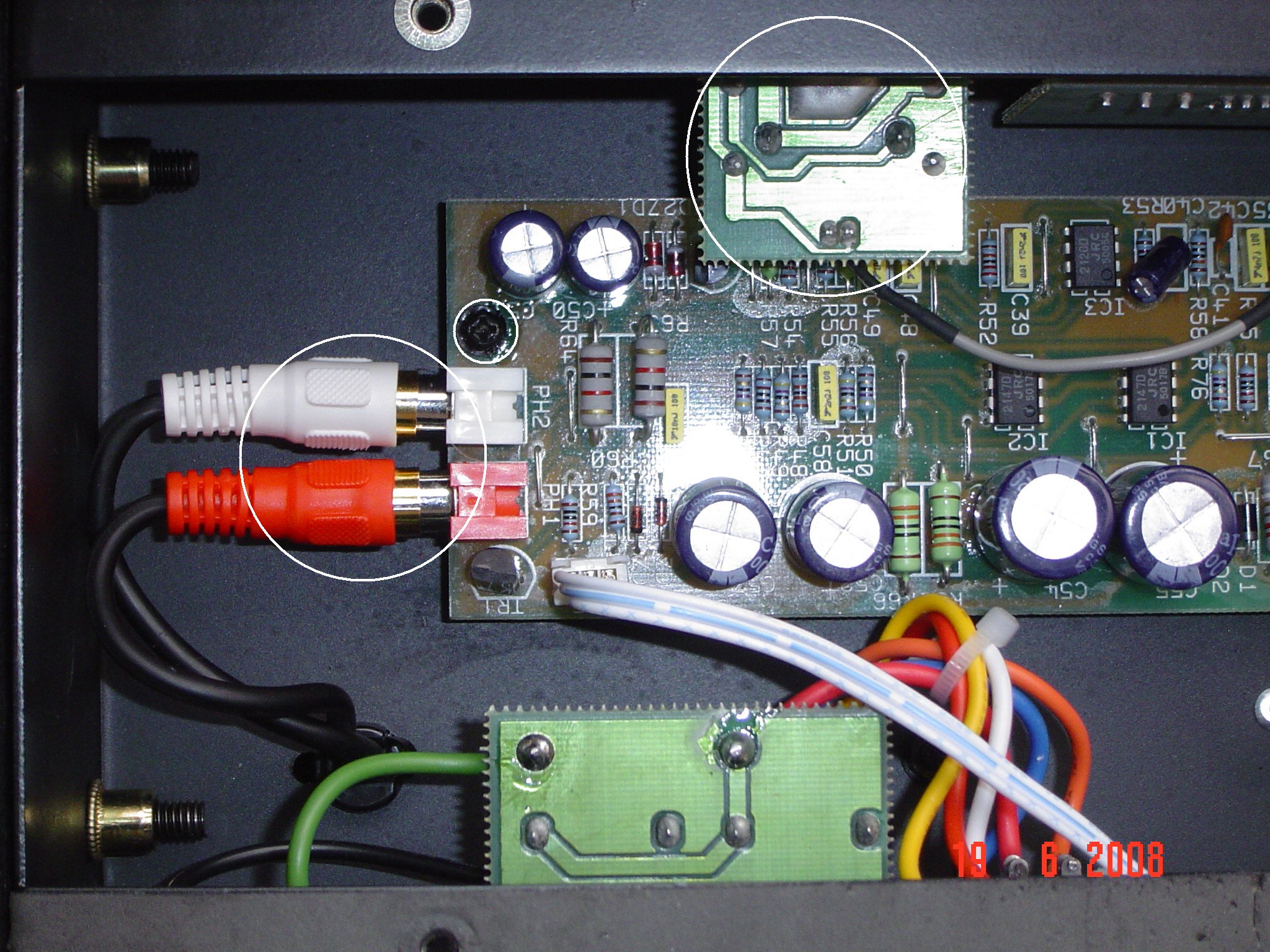
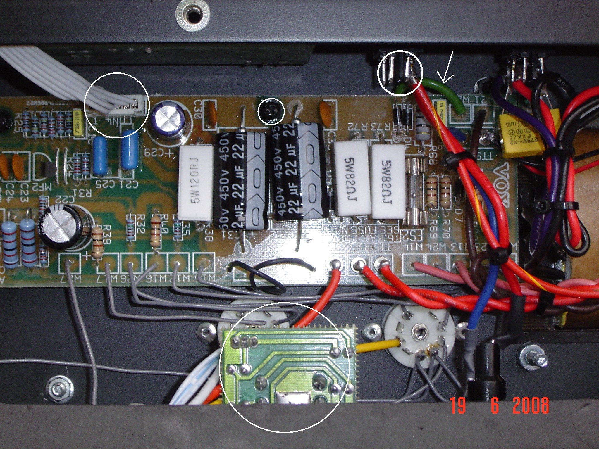
To access the main PCB board do the following: (Each procedure will relate to the picture below it, with components that need to be removed circled in white. Click on the pictures to enlarge them)
- Remove all the screws, the red and white plug (reverb send/return) and the input jack PCB board. Remove the input jack PCB board by removing the plastic nut that holds the input jack in the chassis. The board will slide out.
- Remove all the screws and disconnect the two connector plugs circled. Leave the small connector that goes to the input jack PCB board, this does not need to be removed.
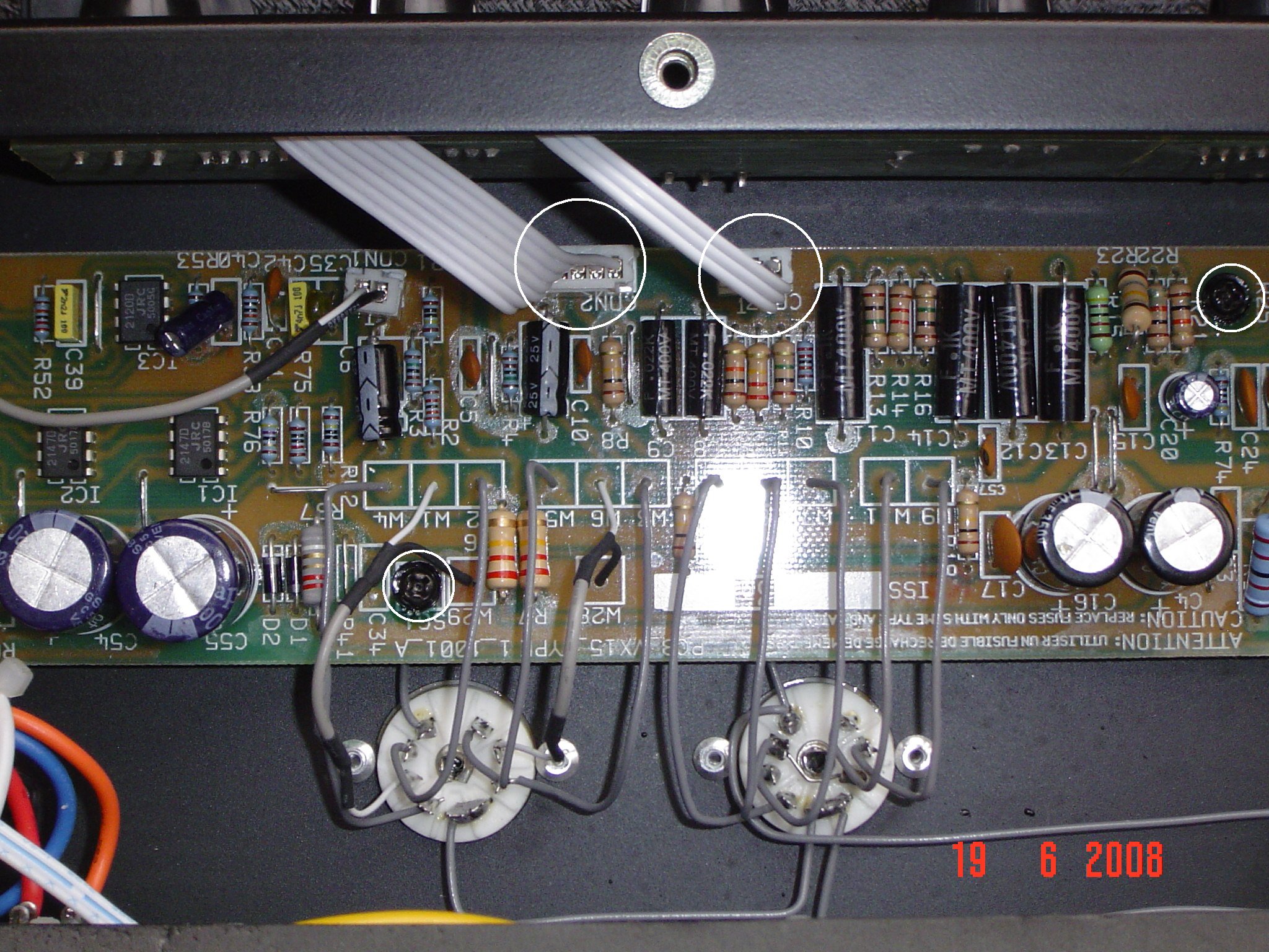
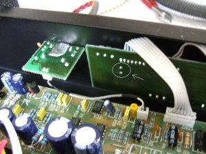
- Remove all the screws and the connector plug circled. You’ll notice a white arrow pointing to a green wire, follow the wire to the chassis and remove the screw and nut that holds the wire to the chassis. Remove the foot-switch PCB board which is circled at the bottom of the picture, using the same method as the input jack PCB board. Tuck the foot-switch PCB board down, vertically, along the chassis. De-solder the wires from the standby switch.
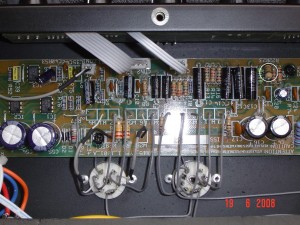
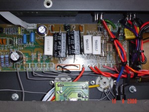
- Remove all the screws. This picture shows the power transformer. Along the wires are cable ties that neatly bundle the wires together, cut these cable ties to free the wires. Note: Yours will not look the same as the picture, as I have fitted an after-market power transformer, however it should be similar. Your cable ties will most likely be white in colour. The white arrow pointing to the green wire is the same wire as described in the previous step.
- Now, carefully grasp the PCB board with one hand at each end and slowly manoeuvre it to the right a little bit, to clear the power switch. Now gently rotate the PCB board away from you. You should be able to rotate the PCB board enough so that it is sitting vertically. Remember that input jack board? You should be able to hang it off the other side of the chassis now, out of the way. I use some sticky tape at each end and in the middle, to hold the board while I work on it. This should now give you enough access to the solder side of the board to de-solder components etc.

Bright Cap Mod
If you’ve ever thought that your AC15CC sounds very ‘harsh’ and ‘brittle’ with overdrive pedals, this mod is for you. Basically the ‘bright cap’ is a capacitor that sits across the Top Boost volume control and lets high frequencies through at lower volumes. As the volume is increased it has a lesser effect. The stock value is 120pF, far too high in a Top Boost circuit. 68pF is considered a good all round value, or most people remove it completely.
If you are more adventurous, you can install a switch to toggle between a few values. I’ve removed mine completely and find it works well, as you can still dial in plenty of highs with the treble control. The good thing too is that this mod is probably the easiest to perform, as you don’t even have to pull the chassis to do it.
With the amp lying face down on the floor and the pack panel removed, look inside the chassis. The bright cap is located on the ‘pots board.’ Next to the input jack is the Top Boost volume control, the bright cap sits across this. Circled in the picture below, is the two pads where the capacitor is soldered too. De-solder these two points and the capacitor will drop out from the other side, you don’t have to remove anything else. Easy.
Tone Cut Mod
The AC15CC does not come with a tone cut control installed. Instead, it has a fixed value resistor which is set at 220K. This value simulates the tone cut control set at ‘no cut’ so the maximum amount of top end is allowed through. In my opinion, a Top Boost circuit needs a tone cut control to help tame the top end. You can install a pot so that you have a full tone cut control like an AC30. I have dropped the value of the tone cut resistor to 180K, which simulates the tone cut control set at about 10-11 0’clock, roughly. I find that with this setting and the tone knob on my guitar, I can keep the top end in check.
To perform this mod you need to follow the ‘Accessing the PCB Board’ guide above, as you need to access the main PCB board. Locate the resistor R23, circled in diagram below, and remove it. Replace it with the new resistor value of 180K, or lower if you desire. I used a carbon film 1 watt resistor here. If you decide to use a pot instead, solder the wires from the pot here in place of a resistor. As the reverb on this amp is quite woeful, removing the reverb pot and replacing it with your tone cut pot is a good idea, if you don’t want to drill new holes in your chassis.
V1 Plate Resistor Mod
This mod is basically swapping a resistor out for the value that was used in the original Vox amps. It gives the amp a little more fuller/ warmer sound, a bit more bite and a smoother breakup into overdrive.
This requires access to the main PCB board, so follow the ‘Accessing the PCB Board’ guide above. Once inside locate the resistor R6, circled in picture below, and remove it. Replace R6 with a 220K resistor. I used a carbon film 1 watt resistor here.
Note: The picture below shows both the R6 and R7 resistors circled. Only the R6 resistor should be swapped out for a 220K resistor.

Choke Mod
The AC15CC uses a 1K resistor just after the rectification stage as a current limiter, instead of a choke. Benefits of a choke include hum reduction, better intermodulation in the signal, reduction in ghost notes as well as changes to the response of the amp. A high end choke costs about $30, so it’s not an expensive mod to perform, although it does require drilling into the chassis to mount the choke.
This requires access to the main PCB board, so follow the ‘Accessing the PCB Board’ guide above. Locate resistor R71, it is a big white resistor. Remove it, the wires from the choke will now take its place. Mount the choke on the chassis, run the wires through and solder them in place of R71 (highlighted in picture below). Unfortunately I did not take pictures of the mounted choke. Next time I have the chassis out I will take some and post them. There is plenty of room on the chassis to mount the choke, so finding a spot is easy. Just take care when drilling through the chassis, so that you don’t damage anything.
Note: Swapping the 1K resistor with a choke will result in a higher B+/HT voltage. If you swap in a choke, you should also consider increasing the values of the screen/grid resistors on the power valves, otherwise they will have too high a voltage on them. This will result in decreased lifespan of your power valves.
‘Standard/ Custom’ EQ Mod
This mod basically replicates the ‘Standard/Custom’ EQ switch, that is found on the AC30CC. ‘Standard’ mode makes your tone controls more interactive, as opposed to ”Custom’ mode, which makes your tone controls less interactive. Both modes are ‘correct’ depending on what era and what model Vox you look at. In the stock form, the AC15CC is like having the switch set on ‘Custom’.
This mod involves the ‘pots board’ and can easily be performed without having to remove anything at all, as you can make the connection on the solder side of the board, which you can easily access.
All that his mod requires is linking the unused lug of the bass pot to ground. The easiest way to do this, is to use the ground lug from the volume pot of the Top Boost channel. You can easily identify the ground lug of the volume put by using a multimeter, and doing a continuity test to ground. You should also be able to see which lug of the bass pot is unused, as there are no tracks leading to/from this lug.
A good idea is to fit a toggle switch, allowing you to swap easily between both settings, just like the AC30CC.
Conclusion
Thus concludes the mods that I have currently completed on my Vox AC15CC. There are many more mods that could possibly be done and I will continue to update this article as I perform them. I hope this has been useful to you – have fun working on your amp to improve your tone. If you have any mods of your own, or have any interesting experiences with modding your amp, do leave a comment and let us know.
Hi Dave, great article! Are you able to post a picture showing the location of the valves please? ie. which valve is V1, V2, etc.
Good point Ian. I’ll update the article with more detail on the valve placement.
I can only get photos next time I have the chassis out. The placement of the valves is to hard to photograph whilst still in the amp.
Had the chassis out to change the power tubes, so took a picture of the chassis and added it to the article.
Hi Dave, thank you for the great article. You were right ON the weakest points of the VOX AC15 in your mods, so now this is my Bible for the following weeks. Perhaps, here is one more mod I am working currently on. I have a project to remove the amp from the speaker cabinet, make it shorter (18-3/4″ across) and place it into my gear rack right under digital effect processor. So, I have full control on sound right under my fingers. The remaining cabinet from the amp I use as a speaker cabinet but modified also in order to make it closed for tighter sound. If you are interested, I can share a picture. In fact, dimentionally the shassis is very close to rack dimensions and even removing both PCB was no nessesary!
1 hour work to move some wires inside and another hour to cut out the exessive metal from the sides. I even mounted the amp to the rack through holes on sides of the front panel. Just made front wider, about 19-1/2″. Now no more microphonic issue with valves as it was before even under moderate volume of AC15 combo.
Best Regards,
Alex, Toronto, CANADA
Hi there Alex,
Thanks for stopping by and posting a comment.
I think the only mods left, to fully iron out the weak spots for AC15, is to change all the coupling caps to Sozo’s, and to replace the output transformer with a Mercury Magnetics. After that I think the amp would be right up there tone wise, although right now I’m very happy with how my amp is sounding.
How do you find the heat dissipation with the chassis mounted inside the rack unit? Does the heat dissipated affect the digital processors sitting above, or were you able to design it so the majority of the heat is dissipated through the front and back?
Hi Davivd, you’re right to the point! All these issues are concerning me too. First of all I was going to cover open side of the chassis with a heavy gage metal plate to prevent any interference with other equipment in my rack. Do you think that aluminium foil will work as much as effective?
Still concerned though, because when I removed the amp from the cabinet my guitar began producing more feedback noise. I do really worry about its behaviour when the amp intalled into the rack. I have finished all re-wireing to keep everything within rack size, relocated input jack on opposite side, installed 8/16 Ohm switch on the front panel using previous Input jack hole and ready to cut the chassis with a grinder. Pictures are on me!
Another question though. As soon as all resistors are accessible (i.e. visible), can I just cut them out with the side cutters and replace them without removing PCB at all? I know, it’s not pretty,but I had already bad experience with overheating PCB while resoldering the elements.
Cheers from Toronto!
Alex Smirnoff (Vodking)
Hi Dave, here is the answer on your question. I have installed the amp under the digital processor and it’s dead quiet! The heat dissipation problem doesn’t seem big yet, but I’l keep my eye on this.
Another tip to all. I use microphone preamp by ART with variable impedance on front of VOX. It gives me extra gain stage and more variety in distortion and clean sound. I am more than happy with the sound, because due to preamp I can make it sound darker like ORANGE or more sustained like MARCHALL on any volume level. That was the reason why I have finally chosen this CHEAP chinese amp for my project. The amp itself does not impress me much.
Cheers,
Alex
Hi Alex,
Good to hear it’s working out well.
Although not the most ‘elegant’ way of doing things, you can go about swapping resistors the way you mentioned. Although I’d be careful that when you re-solder the resistors, the connections are good and solid. You shouldn’t have any problems overheating the PCB though, if you’re using the correct iron at the correct temperature. I use a 40W temperature controlled soldering station set at about 330 degrees and haven’t had any problems yet. I bump the temperature up more, when de-soldering the ‘lead free’ solder that they use, as lead free solder usually has a slightly higher working temperature.
Aluminium foil will work in trying to eliminate interference. Maybe go over a couple of times to give a thicker layer and see how it works out.
Dave
Thanks for the valueble tips! I’ve got even better idea! If the goal is to reduce the resistor value from 220K to 180K, how about to leave the current resistor “as is” and to add another variable resistor in parallel? At this point less work involved and you will never go higher than factory parameter.
I have another question for you, though… I play through a speaker cab with 16Ohm Blue Celestion in it. Amazing speaker, BTW! So, I have found that when amp set on 8 Ohm output the cab sounds better, brighter, louder, tighter, whatever, compare to “obviously correct” switch setting on 16Ohm. Could you double check or at least theoretically explain my observation ( I would think in oposite way, that’s why I need the second opinion)? Another question is can I actually leave this switch on 8 Ohm as my prefered sound setting while using 16 Ohm amp? I know, it’s not healthy for tubes and tranny, but can it really bust them up and kill the amp after all?
Regards,
Alex Smirnoff (Vodking)
Sorry, just one correction to the last post. You have to read: “…. while using 16Ohm speaker?”. 🙂
Cheers!
Currently I am adding channel switch to my “racked” VOX. After that I’ll send you the photos. Waiting for your reply!
Alex Smirnoff (Vodking)
Hi Alex,
Yes…In fact it is very common to solder another resistor in parallel to drop the resistance down, to save pulling the PCB out. This is also done with capacitors to change values.
Regarding your speaker set up. It’s fine to run the amp set at 8-ohm into a 16-ohm load, no problems there. You can run into problems though if you go the other way, say a 16-ohm tap into an 8-ohm speaker.
First off – great page. I’ve been searching for mods for my AC15 and this has been a godsend! I performed the Bright Cap mod the day I found this page and really loved the results – definitely more pedal-friendly.
I’m about to attempt to install the tone cut pot you describe and I have a few questions:
1 – Will a 250k pot do the trick?
2 – You describe replacing the reverb pot with the tone cut pot – could you go into a bit more detail about that? Sorry – still new at working on amps…
Any help would be much appreciated!
Hi David, I’ve sent the latest photos of the “racked out” VOX AC15 to your e-mail. Feel free to share those pictures on your web site. Cheers!
Alex Smirnoff (Vodking)
Toronto, CANADA
Hi there ShinnickRelay,
Thanks for dropping by and checking out the article.
The bright cap mod really does work wonders doesn’t it. What guitar are you using? I’m currently experimenting with different capacitor values for the bright cap. At the moment I’ve got a 56pF in there and find it works really well when I’m playing clean on the neck pickup of my Les Paul. I’m still undecided about whether I’ll leave it in there or not as I’m not sure if I like the tone when I use pedals. Although not harsh like the amp is stock, there is an ever so slight ‘fizzyness’ in the top end that I’m hearing. Maybe I’ll try a slightly lower value.
Regarding the tone cut pot, a 250K pot will work fine there, just make sure you get a logarithmic one. They are labeled with an A in the front, so the pot will say A250K on it.
If you don’t use the reverb at all, you can replace the reverb pot with the 250K pot, for the tone cut control. What this means is that you’ll have to remove the pots board from the chassis and then de-solder the reverb pot from the board. Then mount the 250K tone cut pot in the hole that the reverb pot used to sit in, and run the wires around to where the tone cut resistor was on the main PCB board.
To remove the pots board from the chassis, you’ll need to remove all the chicken head knobs from the control knobs and then remove the little nuts that fix the pots to the chassis.
This takes a bit more work, but then you’ll have a dedicated tone cut control. I was planning on doing this before, but am happy with the 180K resistor swap I did, so I think I’ll leave it out for now.
Let us know if you need any more clarification
Dave
[…] has written an article on various modifications performed to improve its tone and playability. This Vox AC15CC mod article aims to be a convenient reference resource for those wanting to perform their own mods on […]
Thanks a bunch for your help thus far! I’m actually enjoying working on this thing. I’m halfway done with the tone cut – just gotta put everything back together now…
While I’ve got the board out and whatnot – you had mentioned changing the coupling caps over. What values did you change to (or did you change them)? Where are they located on the board?
Thanks again!
[…] article is from GuitarPug.com… Not satisfied with the stock standard VOX AC15CC guitar amplifier, […]
Hi there ShinnickRelay,
The coupling caps don’t change in value. They remain as per the schematic.
The change is to swap them out for better quality caps, as the coupling caps do play a role in the tone of the amp.
The brand that you should look for is Sozo.
Dave
Forgive the newbie…
but I’m not quite sure how to wire up the 250k pot for the tone cut. Does Pin 1 go to ground and the other two to the spots on the board where R23 was? Thanks again for all of your help!!
Hi there,
what you want to do when installing the 250k Pot, is to wire one of the pads to Leg 3 and the other pad to the wiper (middle leg) of the pot. The other leg can be left untouched. These are the pads from R23.
This should give you 250K Ohms when you have the pot at minimum, which is giving you zero cut. As you turn the pot up, the resistance will decrease, giving you more cut, or less high end.
If you’re unsure which leg is which, get a multimeter and wind the pot all the way down and measure which legs give you 250K Ohm resistance.
It doesn’t matter too much if you get it around the wrong way. All it means is that the Cut control will work oppositely, it won’t damage the amp in any way.
Hope that helps,
Dave
You are a stud. Final question: the coupling caps – correct me if I’m wrong: but you would replace C9, C11, C13, and C14?
Yeh….those are the caps to change out. Basically you want to change the caps that are directly in the signal path.
I would also change out C8 (for ‘completness’ since your changing out C9) and C15 (the cap that sits in the tone cut circuit).
C5 and C10 are also in the signal path and could possibly also benefit from being swapped out, but you won’t find Sozo caps in those values. You could experiment with Silver Mica caps in those positions though.
Whether you hear a ‘night-and-day’ difference is hard to say, but all these changes are things that cumulatively work together for the better.
Dave
know of anyway to work a mids control into the circuit? i admit i’ve abandoned my ac15 for a super reverb for this very reason
Hey I know this isn’t directly related but do you know how to remove the pots board?
Hey I see you’ve also replaced the power transformer with a mercury magnetics one. May I ask what advantages are there of upgrading the power transformer as it’s quite expensive…
FINALLY!! You don’t know how long I have looked for the tone-cut mod since hearing about it a year or so ago. Goodbye crappy reverb, and hello to not having my ear drums lasered out by the high frequencies and a usable treble control (rather than having to back it off totally)! I think the bright cap mod sounds like a plan as well as a couple of my drive pedals get a bit ‘fizzy’ some times. Winner, thank you a massive amount for putting these up, I will report back with the results!
There isn’t any real benefit to upgrading to Mercury Magnetics PT. Mine blew, so I was forced to replace it. I decided to go for a better quality one, as at the time the Aussie Dollar was very strong, so I could get a MM for a fraction more than the stock one here.
The benefit comes into play if you decide to do some major upgrades, like adding an EZ81 valve rectifier, or even another channel, as the PT can handle the extra current draw on the secondary taps.
MM do say there is some sonic benefits to a well made PT, but I honestly couldn’t pick anything, so I can’t justify telling people to shell out the $$ for one, unless you have to.
@speed12…..please post back with your results. I’m always interested to hear how others go with their ‘modding adventures.’
You have to remove the chicken head knobs from the pots, and then remove the little nuts that secure the pots to the chassis. The board should then slide out, as the nuts from the pots is what secures the board in place. Then disconnect the little connector leads that fly over to the main circuit board.
Hope this helps!!
@apresvous
I’m not sure about a mids control, but I do have a mod that simulates the ‘Standard/Custom’ EQ switch that the AC30CC has.
The ‘Standard’ setting is like an AC30CC, and makes the tone controls more interactive, but it opens the midrange up a little more.
In the stock form, the AC15CC is like having the switch in the ‘Custom’ setting, so the controls are a little more independant and the mids are slightly scooped.
Both modes are technically correct, depending on what model and what era Vox you look at. Most people prefer the ‘Standard’ setting on the AC30CC though, so it’s worth trying out.
I’ll try and update the article soon with this mod. It’s quite an easy one to do
you said:
Note: Swapping the 1K resistor with a choke will result in a higher B+/HT voltage. If you swap in a choke, you should also consider increasing the values of the screen/grid resistors on the power valves, otherwise they will have too high a voltage on them. This will result in decreased lifespan of your power valves.
Can I ask how important this is to do in your opinion. Will it significantly decrease power valve lifespan? I really don’t want to change things unless it’s really necessary.
If it is, what values would you suggest?
If you are running NOS valves, I wouldn’t worry about it too much, as NOS valves can quite often take higher voltages (Mullards are rated up to 400V). Current production valves are generally rated up to 300V, and you can typically exceed this by about 10%.
In the stock form, the schematic says the power valves should see about 350V on the EL84’s, which is already quite high as far as current production valves go. After fitting in the choke, this would go higher, to maybe 370V which is really starting to push the limits.
I ran my amp for a while without changing any resistors, and the amp ran fine, but I do have NOS 1970’s Tesla Hex Plates. I did use JJ’s a bit too and they seemed to cope as well.
Looking at the schematic, resistors R32/R35 are 1.5k and R39/R40 are 100ohm. These should be changed to 2.2k and 470ohm respectively. I used 1watt carbon film resistors. These valves are suggested by a well known amp tech over on the Vox forums, as they run things a bit ‘cooler’, but keep the ‘correct’ sound. Going too high on these values will start to alter the sound of the amp.
After I fit a valve rectifier, I’ll re-asses my B+/HT voltage and possibly go back down to the stock values, as the valve rectifier should drop the voltage down a little bit, compared to the solid state rectifier. For the time being I have swapped in the higher value resistors, to protect my power tubes a little bit, and haven’t noticed any change to my tone. My power tubes now see a voltage of around 330V.
How hard would it be to replace the input jack with one of better quality and get rid of the pcb board jack altogether? Say, replace it with a Switchcraft jack.
Honestly, I haven’t really looked into it, as I’ve never had an issue with the jack on the amp. I guess if you wanted to, it wouldn’t be that hard, as all you would have to do is trace the schematic and look at where the tip and sleeve have to connect to. You would still need the PCB board part though, as there are components on there. You could pull of the PCB jack, solder the new on to the PCB board with small wires, and just mount the PCB board somewhere on the amp chassis.
The key with plastic input jacks is to makes sure the nut is done up properly. Too loose and the nut will wiggle free and the jack will fall into the chassis. Too tight and you’ll strip the thread of the jack. A rule of thumb is to tighten the nut finger tight, and then use a spanner to go another 1/4″ turn max.
‘Standard/ Custom’ EQ Mod ???
There is an error on your photo?
On your photo, this is not the bass pot but the treble pot which is connected to ground ?
My mistake, you are quite right.
The instruction is correct, as It is the bass pot that must be connected to ground, the picture showed the wrong connection. This is what happens when you try and draw things from memory, without looking at the proper layout!!!
I’ll try and post a photo of my amp with the wire in place as soon as possible, as I don’t have a clear enough picture of the ‘pots board’ on hand, to draw in the correct connection.
Thanks for picking up the error.
Thank you to you for these good mod !
I change the bright cap for a 33 µF, i change the R23 resistor by a pot for your Tone Cut mod, and finaly i am happy with Standard/Custom EQ Mod !
Thanks.
Well I did your mods and what can I say, I’ve finally tamed the top end and am much happier with the sound. Now my question is, what is there left which is reasonable to do, say anything to fix the weak bass response? And is swapping out caps for sozo’s really worth it?
Hi sebastian,
How old is your amp and are you using the stock valves? Weak bass response is sometimes a sign that your power valves are starting to wear out. Maybe try some JJ EL-84’s and see if that helps improve your low end. JJ’s are recommended as an improvement over the stock valves that the amp comes with.
Sozo caps are recommended as a good upgrade, as they also help to smooth things out. Many people who have upgraded their caps noticed an improvement.
In terms of other mods to do, have you done all the mods in the article? All the mods are fairly straightforward and cheap to do, so I’d recommend them if you are looking for more ‘tweaks’ to do.
Reguarding v1 plate resistor mod R6, is this one resistor or R7 also?
Hi Barry,
In the AC15CC change ONLY the R6 resistor. I originally did change both, but the stock value is better and as such should be left that way. My amp now has the stock value back in there and only R6 is at 220k. It won’t actually damage anything running R7 at 220k, but the stock value is fine, so there’s no point in really swapping it out. R6 is the key resistor here for the change.
The AC30CC is different though and both R6 and R7 benefit from being swapped out 220k.
I think the confusion probably arose as I originally had both resistors at 220k, which is reflected in the picture, but the instructions only call for a change in R6.
Hope that helps clear things up,
Dave
Dave, thanks for clearing up the plate resistor mod (R6). Just wanted to be sure, as the instructions said “change resistors R6”, which made me check the pictures. I’ve completed all of your mods and the amp sounds great. I’ll keep watch for anything new. It’s guys like you that keep us all sounding good. Thanks again, …Barry
Glad to hear the mods are working well for you.
I’ve updated the article to hopefully make it a bit more clear and avoid possible confusion for others in the future.
Dave
Hi David,
I recently got my AC15 CC and plan to modify it, I have purchased JJ power tubes and Tung-Sols for the pre’s, and also plan to put in an Accutronics reverb pan. I am also planning to change the output tranny. I am thinking about using a Heyboer instead of a Mercury Magnetics since they are well regarded and much less expensive. Do you know anything about the Heboers? They don’t seem to have anything designed exclusively for the Custom Classic, the ones they make just say “AC 15” . Would an original AC15 tranny fit the Custom classic? Is the color coding on transformers pretty standardized?
David,
I went into my Vox AC15 and heated up the bottom of the pots board and undid C26. I pushed it through with the tip of the soldering iron.
I put the unit back together and if fires up but now the top boost volume does nothing. The master still works, and the tone controls work, just not the top boost volume pot. I hope I didn’t goof up the board by sticking the iron through the little holes of C26 to push them out. Have any ideas?
Thanks,
Ted
I took it apart again and it looks like I probably goofed up the connection between the C26 resister and the volume pot. Is there a way to perhaps lay down solder or use a small wire to fix a striped spot on the printed circuit board, or am I stuck trying to find a new pots board. Also.. If I am stuck… where would I get one?
Hi blueslideguitar,
Unfortunately I don’t know much about the Heboer transformers, apart from the fact that they are a well made unit, and well regarded on the forums.
You should be fine picking up any transformer that’s suited for the AC15, just pick one that’s got the appropriate output impedance configurations that you are after. The fact that it’s not made for the Custom Classic just means that it won’t be a drop-in replacement, so there will be some drilling involved. Usually you’ll need to drill 3 holes as you can use one of the pre-existing holes.
As far as the wiring colours go they are not necessarily standard, so you’ll need to make sure you get a wiring chart from the manufacturer, so you know what wire needs to go where.
Hi tjnugent,
It is possible to damage PCB boards and components if you overheat them with the soldering iron.
Check to see if you have continuity between the connector ribbon and the potentiometer, as this will see if you’ve damaged any of the tracks connecting to the potentiometer (TB Volume control).
If any of the tracks are damaged you can fix them by scraping away the green coating and exposing the copper track underneath. This will allow you to solder directly to the copper track and make a new connection.
Hi David,
I had a guy at the local repair shop jumper the board and it now works well. Looks like I found a guy to do the rest of the mods.
Thanks for your help.
TJ
So far I have done the bright cap mod and replaced the speaker.
The bright cap mod really takes some of the shrill treble out of the amp and for the better.
I replaced the Warfsdale stock speaker with an Eminence Red Coat “Red Fang” 8 ohm alnico speaker. I went with the Red Fang because the price was $149.00 at “The Corner Music Store” in Nashville. The cheapest I found a Celestion Blue was $250. The Red Fang made a huge difference. This is a very balanced speaker that has smooth highs and rounded lows. The mids don’t give you the ice pick sound either. For the budget conscious, the Red Fang is a great choice.
While ordering the needed parts for these mods, I found it a challenge to match capacitor values to the websites that sell them, so I found a neat conversion chart that may help.
http://www.justradios.com/uFnFpF.html
Cheers,
Ted
I’m thinking about doing some mods to my AC15cc1. Do you know if there is a way to increase the treble without decreasing the bass? I tried that EQ mod you talked about and when I cranked the bass all the way the bass signal was cut off. Can I mod the EQ so I can crank both Bass and Treble together?
REVERB MOD:
I have performed this mod easily and quickly and with great results:
Open up the bag that your reverb tank sits in (requires you to unscrew a few things)…then pull out the RCA cables. The Beltron reverb unit is screwed into a block of wood.
Remove the small block of wood and attach it to your new Accutronics 8EB2C1B unit (the holes match up perfectly).
Re-attach the RCA cables then put the tank back in the bag. You can get the new reverb at tubesandmore.com. The stock verb tank has a killer as in bad tank that has a delay of like 10 seconds. The new one has like 2.
David,
Great article. I have an AC15cc1 (April 2008). Have fitted UK Celestion Blue 8 ohm about six months ago. The reverb and tremolo/depth controls no longer work….recent failure. Are they on the same circuit or is it coincidence?
Any thoughts?
Regards
Hi David,
I have just purchased a set of Sozo caps. It specified that they were for an AC30. They look the same as the AC15 apart from c5 and c15 being 400v where as on the AC15 it states that they should be 500v. Do you know if this will cause any problems?
Cheers,
Phil.
I started mods on my AC15CC and ended up with a completely rebuilt amp.
Fitted smoothing choke, fitted EZ81 rectifier, with seperate 6.3v heater transformer.
Fitted an EF86 “normal” channel, fitted controls and input socket in places originally used by trem and reverb controls.
Fitted top cut control in place of standby switch and toggle switch for mains on.
I’ll get some info on my site!
Hi,
Am I able to simply disconnect the RCAs for the reverb if I don’t intend to use the reverb or will this damage my amp? I intend to build a box for the chassis so that I can use it as a head.
Cheers
For the Tone Cut mod, where will I find a 180k 1w carbon film resistor?
Thanks,
Jak
i have a vox ac15cc and i want to upgrade the speaker to a celestion alnico blue. should i get an 8ohm or 16ohm and whats the difference in sound?
Hello David, I was wondering if you could help me out with a question I have about modding Treble Cut circuits. I own a Vox custom Classic Ac-30 (the one with two channels and all the switches and knobs) with Wharfdale speakers and I recently purchased a 50 watt “1987” Lead circuit Plexi clone. With My Vox, keep the treble at 0 and and the tone cut on full, allowing me to get a really sweet and creamy sound. But with the Plexi, I find that it has too much treble to sound good, even if I plug it into the lower inputs, and keep the presence and Treble at 0. I thought that maybe if I could modify the Presence circuit to be more like the Tone Cut circuit, I could get similar results from the Plexi. The problem is, I don’t even know if both controls work in the same way, or if they are relatively in the same place in the circuit. Is it possible to modify the Presence control to work like a Tone Cut control on a Vox, or to just completely remove the presence pot and all of it’s components and install a Tone Cut pot?
Hi Dave, great article. I just acquired an AC15CC2 and really like it. I did notice today for the first time a strange odor, not tube odor, like parts getting very hot. I removed the rear panel and did some checking and found R72 and R73 very hot. These are the two resistors off of the Power Transformer by the standby switch. Now I realize they should be warm to the touch, but hot ? not sure. Any comments would be greatly appreciated. The amp functions fine but the appearance of the strange odor has me wondering.
thanks
Tony from North Carolina
What value choke did you use?
thanks
Just wanted to say thanks for the awesome mods. I did the bright cap and the vplate one and noticed a huge difference.
I’m planning on doing the tone cut one too. Can I use a .5 wat pot? seem to have trouble finding a 1w one.
Hi,
I’ve done the bright cap on my 2007 AC15cc1. Nice one. I’v also fitted a UK Celestion Blue 8 ohm speaker. Nice one.
I’m now looking at the 220k 1w R6 resistor mod. Is it easy enough to do (as simple as bright cap was….I’m pretty decent with a soldering iron)
Could you eleaborate a bit further on the ‘improvements’ expected.
Regards,
Ian Young
Hi David,
would it be possible to use the I/O from the spring reverb for a fx-circuit by modification. Don’t like the original spring and befor i replace it, would be good to know.
Thanx in advance. And by the way, great mods!
sniki
I saw a reference, on another site, to adding a vintage EF86 kit to the AC15. What is this / what does it do? Where would I find one? How is it done?
In your article you say “…you should also consider increasing the values of the screen/grid resistors on the power valves….” Can you elaborate? What value comes in the AC15 and by how much should it be increased?
hey, this looks great. i always thought this amp was to brittle, i don’t own it i have a vox nighttrain, but this one is also a little to brittle.
IS THERE A BRIGHT CAP MOD for the VOX NIGHTTRAIN??
anyone please help me how to do this.
kind regards,
Hello,
I just did the bright cap mod on a vox ac15cc amp. Although, the high end is less harsh, which is nice, now, the volume control for the pre amp doesn’t work and the treble control cuts out when I turn it almost all the way up. Do I have to put a jumper in place of the cap?
Thanks,
Dave
I see someone else had the same problem I did after removing the bright cap. I overheated the circuit board and lost the connection. I fixed it by running a jumper wire. I like the sound of the amp, much better, thank you! Now, I’m thinking about doing more of your mods and this time I’ll take it easy with the heat.
Thanks again,
Dave Abair
How about a mod for an effects loop?
I’m a complete and total n00b that has successfully complete the bright cap mod and I’ve replaced the speaker with a Celestion Blue. I would like to do the tone cut mod but I would like to put a pot there for more control. Would I just put the 220k resistor on the pot and solder the pot in place? Like I said, I’m new to doing mods and want to get it right with one try. Any help would be great. Thanx!
I did the AC15CC tone cut mod and now the bass pot does nothing.
I went back to the original 220k, checked the connection to C15 and R22 and still nothing . Any idea what happened?
Has anyone tried the bright cap mod with the brand new AC15C1 model with the Celestion Greenback? My OD and fuzz pedals sound fizzy through it, wondering if it’s the same procedure.
I wanna mount a choke and found out that a 10H 100mA would fit. What about the Ohms? The one i could purchase quite cheap (germany, 23€) would be 85 Ohms. I know about changing resistors for keeping the voltage low enough for saving the tubes from too hight voltage. The seller of the choke says if those two values (H, mA) fit with the recommended (MM), the ohm value shouldn’t alter a lot.
Would be glad for any advice. Thanks!
Hi, Just wondering if there is a way to attach a foot switch
to go between clean sound and overdrive sound?
Using a distortion pedal does not sound as good as the AC15 with
the gain turned up.
Thanks
I removed the “bright cap” today and it definitely seemed to get rid of the annoying fizzy, brittle sounds when the amp is overdriven. I’m so glad I found this site. However, I do have to say that removing the cap was not as simple as stated as the cap didn’t just “drop out” after putting the iron on the solder joints. I ultimately had to take the knobs off and move the pot board so that I could pull the cap off the board (after I removed the solder on the back using solderwick).
I’m planning on replacing the reverb tank and am hoping that it will make a big difference. Did it make a huge difference to any of you? I hope it sounds closer to the AC15C1 I played in the store recently. I has a really good surf guitar sounds when the reverb is cranked almost all the way.
Also, I’m not sure about upgrading the speaker or not. I really would like to play an AC15 with the alnico blue in it to try to hear the difference. I am curious as to what speaker breakup sounds like and if it is a desirable sound (since the alnicos have a lower wattage and therefore breakup at lower drive level).
Good to see you back. I am about to undertake the V1 R6 resistor mod using a Richard Allenby carbon film one. I have read onj another forum about adding an earth to the 3rd bass control tag. Any comments anyone?
Oops sorry, meant to say Allen-Bradley. Of the two resistors circled in the piccy, is the R6 on the right hand side? I assume the circuit board has it printed as such.
I note your article above regarding the eq mod. Apologies for asking.
AC15CC – “Convert Master Volume to Cut Knob” Mod
A friend of mine has the AC15CC and wanted to do some mods to it so we used this website as a starting point. He wanted to remove the Master Volume and add a Cut knob like the AC30. I was able to convert the existing Master Volume to a Cut control by removing one resistor then adding two components to the existing 500kA MV pot. The cut control is very useful and much more useful than the MV imho. Here’s how you make the changes if you are interested:
Parts:
– 470k ohm resistor (1/4 or 1/2 watt)
– 0.01uF cap (500v)
For this mod i’m calling lug 1 of the MV pot the lug that connects to pin5 of CON4 in the schematic, lug 2 and 3 are the lugs that are shorted on the pcb (connects to pin6 of CON4 in the schematic).
1. Snip or desolder R23 from the main pcb and remove it to eliminate the “fixed” cut circuit.
2. Remove the satellite pcb containing the pots.
3. Remove all solder where lug 1 of the MV pot (VR10) connects to the pcb. Make sure lug 1 is now loose in the hole (ie no solder at all).
4. Carefully bend the leg of lug 1 up and out of the hole then under the pot and leave it “flying”, this way you can return it to stock if desired.
5. Install the 470k ohm resistor across lugs 1 & 2 of the MV pot . I installed the resistor in the small square holes at the top of the L shaped legs (this converts the pot to roughly 250k)
6. Now install the 0.01uF capacitor between lug 1 of the MV pot (i used the round hole above the lug) and the point where lug 1 used to connect to the pcb. I was able to install the capacitor under the MV pot.
Put everything back together and voila you have a great cut knob instead of a MV that performs like the vintage AC30 cut knob. If you have any questions don’t hesistate to contact me.
Have done the vox ac15ccmod guide. I followed all the instructions , and the only sound I,m getting is a big humming noise? All the resistors are the correct values and all solder joints are clean. The only thing I can think of is the choke? I used a weber universal 9h@120ma. Any suggestions or tips on what may have gone wrong? Thank you any information would be great full. Mike
Within the next couple of weeks I will undertake both the choke and V1 plate resistor mods. I have purchased a Hammond 158M choke (10H @ 100ma). With regards to the 2no black leads attached to the choke, I assume that the choke is non directional so to speak and that the black leads can be soldered into either of the points vacated by the 1K resistor?
Just have to say THANK YOU. All I did was remove the Bright Cap and my Geranium OD, Big Muff and Yamaha Distortion pedal SOUND GOOD on the Leads. That stock VOX AC15 brittle/chimey treble sucks! ( I used to hate my VOX before I came to your web site.)
Next is Weber Silver Bells 12″ speaker upgrade $190 + ship.
After that I may do the other upgrades.
I play Floyd, Zep, Seattle scene, 60’s hard acid rock.
http://www.techwebsound.com
Technicolor Web of Sound – it Rocks!
FWIW – if any of you get tempted to pick up an AC15CC1 on special due to the new AC15C1 model, like I did, some of these mods make it a much more usable amp. Pre-mods, and even post bright cap removal, I was still getting a Laser Beam of Deathtreble® out of the dome of the speaker with a mic (or positioning myself right in front of the amp where i could hear what the mic was). And this was using humbuggers, neck PU, treble rolled waaaay back.
The thing that finally seems to have licked it is putting in the tone cut pot for a variable tone cut. Now if I want the LBoD®, it’s there, but if i don’t (like playing rhythm) I can cool it off.
My only suggestion is to NOT use an A250K pot, but instead use a linear taper pot. The explaination is better done visually with a graph, but in essence, if you use an audio taper pot in this instance, you have to turn it up to 5 or so before you’ve gone from 250 (the max value) to 220 (the stock value). So, the difference doesn’t become audible until 6 or so, and that leaves from 6-10 to make the adjustments. With a linear taper pot, you hit the stock value around 2 on the dial, and the adjustment sweep is much wider (2-10), making it easier to dial in. The tonal range is exactly the same, it just happens across a wider variety of numbers on the dial.
wondering if anyone can help: I am wanting to replace the caps in my AC15h1tv. But I really don’t understand which caps I should change. The schematics are at:
www.*blue*guitar.org/new/schem/vox/ac15htvh1_handwired.pdf
could anyone help me out? I would be very grateful
thank you
Does anyone know if the AC15VR has the same Bright Cap that can be removed?
WELL, Thats it i suppose,I am in the market for buying a new amp,probably 20 or 30 watts,I have been reading reviews in harmony central etc,and it seems to me im wasting my time ! all i see is mods this and mods that, ……….. so why on earth dont the amp manufacturers just build their amps properly ! ……… to be honest im so pissed off with what i have been reading i dont think i will bother with the expense of purchasing a new amp, im too afraid to ! especially the dopey money that is being asked for amps these days, ………… and still you might purchase a box of expensive unreliable rubbish ! why does it have to be like that ?
WELL,I AM GOING TO STAY WITH MY 31 YEAR OLD MARSHALL MASTER VOLUME MK2 COMBO ………. WHICH HAS NEVER LET ME DOWN,UNTIL SOME OF THESE IDIOT MANUFACTURERS START TO DO THINGS PROPERLY INSTEAD OF CHASING MONEY !
…….. JUST CANT BELIEVE THAT A NEW AMP SHOULD BE MODDED,HOW STUPID IS THAT ?
LES.
Hi, i did the BRIGHT CAP MOD and removed the bright cap completely.
I noticed one thing, though I’m not sure if it has been there before:
when I use the treble tone control and put it to the max, the bass part of the sound kinda disappears. everything else works ok.
Now the problem is that I cannot remember – does this also happen on a stock AC15?
Haviing trouble with the custom/standard mod. I soldered the unused bass connection to the top boost volume ground (I checked to make sure it was the ground connection) and when I turn it back on the bass adjustment does nothing, the treble works but nothing with the bass. I saw one comment that said you had a picture that showed the treble connection connectd to ground but you said that was wrong. Any suggestions?
Unless im doing some thing insanely wrong, which i dout. The Standard and custom EQ does absolutely nothing for me, it has no effect on the tone at all!!!
David mate I’ve emailed you twice and still nothing from you dude. I will cry if I cant get it to work. I’ve already installed the switch into the chassis!!
Hello,
I have an AC15CC for some years, I have used it in concerts a lot of times and I never had a problem. But now I´m in troubles: tha input jack was very loose and I opened the back of the amp for fixing it, and I didn´t remember to close it, so sadly that the next week I went to rehearsal place and I discovered that the input jack with the PCB board wasn´t there, it was stoled! What an incredible thing! It´s a big problem because I cannot use the amp and I cannot find replacement, I´ve been looking in google but nothing… So please, do you know any solution? Or at least give me a picture of the board for trying to build myself a board like this? Thanks in advance
I just wanted to say thanks for posting all the great info for people with the desire to improve their amps! This is a very helpful page!
Hi Dave,
Thanks for the informative article which I found whilst performing repair work on one of these voxes. Just wondering, from the photo it looks as though R72 and R73 are the 82R as designated on the schematic I have. However, I pulled 220R resistors out of these positions, both O/C and both causing board burnout and arcing to ground. They were super cheap resistors and didn’t quite look ‘factory installed’ if you know what I mean. The only thing is, the customer is adamant that he bought the amp brand new so someone is either lying to him, the amp was messed with in the store or Vox had a revision at some point with this value, possibly indicated by Rev2D in the schematic notes. SInce Vox and their Australian distro Yamaha seem to be really unforthcoming with support email addresses I thought I might check here to see if anyone has encountered this problem before I try to wade through the appalling mire that is any Non-American amp company’s technical support services.
Cheers, gavinv@valvolux.com
It’s very simple.
I changed the C5 capacitor (470pF) in a10nF capacitor. The amp is now perfectly in balance. I have now the needed low tones. The bass and treble pot are both in 12 hour position for the best result (with the Wharfedale speaker).
Peter
When doing mods to the Vox AC15CC1, try to bear in mind that this amplifier is not exactly the same amp as an old, original AC15.
If you compare schematics, the newer amps have quite a few differences, and some mods will work better than others.
Because the newer amps have solid-state tremolos in them, and the tremolo is in a different place in the new amps, there are a couple of 10K resistors isolating different things from each other. The Master Volume on the new amps is really where the “Cut” control should go, for example.
Also, the tone controls in the original amps were a “cathode follower” type of arrangement, with the second stage of V1 being used as an impedance converter, which adds no gain. In the new amps, the tone controls are connected to the high-impedance anode of the tube stage. This stage adds quite a bit of gain. This is almost like taking an old, original AC15 and modifying it by adding an extra gain stage.
So, anyone trying to get the “original” AC15 sound would have to start by rewiring the stock amp to the old specs first. Then, you’d have to add the right choke, an EZ81 rectifier tube and everything that goes with it. The cabinet material also makes a difference, and of course, the speaker.
So, with my AC15CC1, I just approach it as it’s own amp—not necessarily an AC15.
Thank you so much for writing this guide! It is ‘the’ tome on Vox AC15 modding! I followed a few of the mods detailed here: (tube/speaker change and bright cap) and have taken pictures of the process at my blog which can be found here: http://endofthegame.net/2011/09/02/vox-ac15-mods/
[…] journey of me and my Vox AC15 amp. Most of the mods I performed were inspired by the guide found here, you should definitely check it out if you’re considering doing some mods of your […]
[…] From here: http://www.guitarpug.com/2008/06/vox-ac15cc-mod-guide/ […]
Just curious if the bright cap mod can be applied to the older UK made Korg era AC15TB models?
Hi, what a great article…
I have this amp I had real bad luck: someone stoled the input part with the jack and pcb so I cannot use the amp. I tried to use a jack and wires direct to the minisocket with 2 holes but it sounds nothing just some strange noises sometimes.
Please could you help me to fix it in any way to use the amp again?
Thanks for putting together this guide!
I have pretty much gone through all these mods on my amp and thought I would share my experience.
I picked the amp up cheap by accident, I put in a low bit and won.
Looks gorgeous and well put together. A really nice pcb and I have to say I was pleasantly surprised.
Sounded absolutely rubbish in a rock band situation.
Was crazy trebley and with any kind of pedal it just turned into fizz.
So at that point I stumbled on your guide.
Bright cap mod instantly sounded better, pretty easy to do. I did it with some solder wick from the back and the cap just fell out.
The reverb it is too long and unusable so dropped in the recommended reverb. Massive improvement, have in permanently on now.
Didn’t like the speaker either so dropped in a Greenback. Sounds great.
I replaced everything in the tone path with silver micas and mallorys and that made me feel better although didn’t really notice much of a tone change.
The tone cut mod I actually went super low. The value I am using is about 67k. It made a noticeable difference.
The EQ mod is a lot better then the default, much more natural.
The V1 plate resister mod didn’t really work out for me. The recommended values made the preamp go crazy when turned on full so ditched that and reverted to the default.
The choke mod was fun, though has added extra weight to the amp.
I changed the knobs to bone ones, that looks cool 🙂
For valves I went with Mullard reissues for the poweramp and tung-sols for the preamp.
I bought a sweet cover from Coveramp and a vox footswitch and I think the amp is sounding as good as it can.
Will try some VOS tubes when I wear these ones out, and have just ordered a leather handle for it.
The plastic one vibrates like anything for me when it is in the resting position. When it is stretched upright it is ok.
So there you go.
Thanks again for the guide.
You rock!
Hi, Excelents mods my friend. I recently do it on my amp, except for ‘choque mod’ It’s not clear…there are diferent magnitude of units, one is Henry, another is Ohms.. I did’nt understand how do you replace It..
well, thanks for this great guide man.
Kind regards from Argentina.
Pipo.
[…] sounds a little brittle to my ears tho so I may have to do the bright cap mod as described here, Vox AC15CC Mod Guide | GuitarPug if anyone perusing this item has one of these amps I'd love to hear what you think about them. […]
Thank you so much for the info!
I just finished doing the bright cap mod and the improvement was noticable right away. At first I was a bit nervous about doing it myself but the picture pointing out where the caps were positioned made it easy to find the spot to do the unsoldering. 🙂
This is the second thing I have done to my AC15CC1. When I ordered the amp I had the store put in a Celestion Greenback instead of the Wharfedale speaker which also made a nice improvement on the original sound.
With these 2 improvements the amp sounds just the way I like it.
First of all a big thank you to David Buntsma for describing these mods,David you are a gentleman.
I did the bright cap mod to my amp but I had to remove the pots board to help get the cap out,no biggie just a little extra time to do the mod but I had more control over how much heat was getting into the board that way and I could grab the cap and help it out a little.
I’m now considering doing the V1 Plate Resistor mod as hearing how much of a difference taking the bright cap out has improved the quality of the sound coming out of the amp I have to seriously consider the other mods mentioned in this article.
I have a question though if anyone would care to answer…
The mod is described by David Buntsma like this,
Once inside locate the resistor R6, circled in picture below, and remove it. Replace R6 with a 220K resistor. I used a carbon film 1 watt resistor here.
I have a few Allen Bradley 220k carbon composite 0.25w resistors here that are left over from another project so would I be able to use these 0.25w resistors for this V1 mod or do I have to stay with a 1w resistor.
I’m a paint by numbers kind of modder and I’m only learning about the actual science and theory behind the mods as I go along so if anyone wants to help me out by answering that question it would be appreciated,
thanks
Could we have a demo as to how this sounds?
Performed some of these (removed volume pot cap, larger V1 plate resistor (added one 120k in series = 220K) and tone cut – (250k pot- looking at the back cover for a spot to drill the hole). It really helped the sound towards warmer, better eq-ed mids, also the preamp distortion seems to sound better (less toaster, more control). I like the tone cut pot, helps me when I change change guitars, also it seems I tend to shift around some and also go down to a lower resistor value than the 180-120 k resistor values that often are elected/suggested.
Reverb tank – I might change it, thinking along the lines of building an effect loop instead of the reverb, doesnt seem too far fetched.
Also trying an Ecc 81 ! for “better headroom”(valve 1) – read about it somwhere and a friend of mine had a box of tubes..so why not.. I´ll report back after Ive tried it for a day or two..
Steps are easy to follow, nice helpful article!!
Thanks a lot for posting it!
Hi All.
I’m glad I found this website.
About the quality on components in the VOX AC15CC1.
My Amp stared to behave crazy, volume goes up and down intermitently.
all from full volume to silent..???
I started to investigate, and found that the MASTER volume pot was broke, it was suddenly shorted. And since this volumepot is actully shorting the two phases after the phase split tube. a short circuit masterpot means silence!!! So I removed the whole PC that hold the Mastervol and the vibrato ports as weel. And exchanged them to betterquality pots. I prefere Bourns pot, but these values (500Klog and 2,2Mlog) they are hard to get here in europe. I replaced the pots and I was happy playing again……Then I suddenly realised thath the Bas pot did’nt do much when turned!!!
As I was to perform the Trebble Boost mod, I also removed the PC for the Volume Bass/trebble and reverb pots as well. Drilled a new hole for a switch for the BrigthCap (a silverMica 120pF cap). I also replace the original pots with higher quality pots.
I mean , later i measured my Bass pot and it was broke to…
Compared to a standard AC15/AC30 the VOX AC15CC1 has only one channel input, the brigth Channel, with the capacitor C5 470pF specifying the highpass frequency.
On a standard AC15/AC30 that has two input channels, normal and brigth, the normal channel has this capacitor set to 22nF. A big difference to 470pF in the brigth channel.
Has anyone tried to insert a 22nF or something less in place of this C5 in AC15CC1?
I am going to try so add a switch here chosing between lets say the standard 470pF and parralell a 2,2nF and lets say a 10nF. Why not set a regulary multi switch to choose from several values. By parralelling C5 with additiona values will get more tone choises.
A norma AC15/AC30 has the vlume pot set to 1M, and the AC15CC1 has a value of 500K, so I guess that 22nF for a 1M pot is equal to about 10nF for a 500K volume resistor value.
Maybe a change to a 1M pot will help, I dont know if thats nescesary.
Any comments?
Sorry, my misstake . I guess it should be a 0,044nF instead of 0,022nF,
when the 1M pot is lowerred to 500K.
Now I have added a new switch dpdt with a middle off, an on-off-on, giving the possibillity to add to caps in paralell to C5.
I used a 1,8nF and an 22nF giving me a choise off Normal channel and something in between.
Very easy mod.
Just solder two leads to each side of C5 to the switch.
I drilled the hole for the switch just on to of the input jack, so its in the Input box of the panel.
A broader pallete of lower sound. Not to overwhelmomg though. but if you miss the normal channel from the standard AC15/AC30 this is for you. If your looking for the guitar-sound from the song ‘Here, there and everywhere’ by the Beatles…its here. If you want that jazz sound you would probably use the normal input on an AC15/30.
Hello,
great mod page, I just got a used AC25CC1 and I am hooked!
I was wondering if the Tone Cut Mod by replacing the reverb volume pot could also incorporate reverbs foot-switching capability so that you could switch between a fixed resistor and another value based on where the pot is set? Does that make sense and is it feasible?
Thanks for your thoughts on this idea.
Brooks
brooks61@hotmail.com
Thanks for putting together this guide. I’ve followed the same path as just about everyone else.
– treble cap (1st thing done … wow!)
– new set of JJ’s tubes (big improvement over the stock tubes)
– reverb replacement (yippee!! … working reverb) (Accutronics 8EB2C1B)
– speaker swap (got a hell of a deal on a Weber Blue Dog … nice speaker! *huge* difference)
Everything up to this point should be considered absolutely necessary.
Everything from this point on, is a matter of taste IMHO.
The following modifications are a little more complex (as noted else where).
– Tone Cut Knob Mod (pulled out some more of the top end)
* replaced R23 with 180kohm resistor (Xicon 1W Carbon Film Resistor)
– choke installation (significant input clean-up and noise reduction)
* Mercury Mag. Tone Clone installed in place of R71
* R32 and R35 from 1.5kohm -> 2.2kohm (Xicon 1W Carbon Film Resistor)
* R39 and R40 from 100ohm -> 470ohm (Xicon 1W Carbon Film Resistor)
– V1 Plate Resistor Mod (bit more compression and overdrive)
* replaced R6 with 220kohm resistor (Xicon 1W Carbon Film Resistor)
* still debating reverting to stock value
The following is a pretty large change – please use caution – I replaced all the following components (note: your solder skills will be tested doing this, so don’t go into this unprepared)
C3 -> 0.01uF/500V 470pF/500V 0.022uF/400V 0.022uF/400V 56pF/500V <- 50pF/500V 0.1uF/400V 0.1uF/400V 0.1uF/400V 0.1uF/400V .0047uF/500V 0.01uF/500V 0.01uF/500V 0.01uF/500V 0.01uF/500V 0.01uF/500V 100pF/50V <- (Cornel-Dublier Silver/Mica)
I selected Mallory Series 150s over Sprague (Orange Drops). One could substitute Sprague above and achieve a slightly different feel (I would think). Probably a nice experiment … never know, I might do that one of these days.
So …. what does it sound like now? Pretty sweet … to be quite honest. It's not a mid-60's AC15 but once these new components break in (some more), I believe the final tone will be distinctly more VOX-like than what we started out with.
It's also been a whole lot of fun getting back into taking an amp apart and putting it back together (working … no less! 🙂 )
Good luck … and thanks for all the pointers.
Here are the cap changes (sorry about the mangled input above).
C3 -> 0.01uF/500V 470pF/500V 0.022uF/400V 0.022uF/400V 56pF/500V <- 50pF/500V 0.1uF/400V 0.1uF/400V 0.1uF/400V 0.1uF/400V .0047uF/500V 0.01uF/500V 0.01uF/500V 0.01uF/500V 0.01uF/500V 0.01uF/500V 100pF/50V <- (Cornel-Dublier Silver/Mica)
Question about the v1 resistor mod. I tried this mod out and replaced the resistor with a 220k 1/2w. Once I reasembled and powered up my ac15 baraly made a sound (the volume and master had to be at max to hear anything). I quickly reversed the mod and my amp works fine now. Any tips on how to make the mod work properly?
Mods currently done to my ac15cc1: tone cut (with an extra pot), bright cap, and custom eq.
What a great article.
I got the new Vox AC4-1-12, and while it sounds great on the neck humbucker, but the bridge is “shrill”
Would the bright cap mod be appropriate for it too?
Okay, I need your help. I unsoldered the bright cap as directed and no signal get to the amp itself. The tubes work fine and I can hear sound through the speaker, so I know the amp is working What did I do do wrong? It is in the input I believe where the problem is occurring.
so i know this is late in the game, came along this article though and had to try the mods. did all of them at first just the bright cap mod, then i scored a custom run celestion 65W from mojo sound. new tubes, reissue mullards in the inverter, eh in the number 1, JJs in the power section. All those helped out this little guy tons.
I just did the rest of the mods:
choke
tone cut with pot
and the V1 resistor mod for 220K
was gonna wait on the others to see how the choke was working the JJ’s
Problem is now it seems there is way less volume, it distorts really early and sounds terrible. I double checked my joints and nothing seems amiss.
Any thoughts on what went wrong? where to look? any help would be appreciated. I can tell already there is goodness lurking in there, just need to find the bad bit. the tone pot seems to be working all right.
thanks for any helpful reply.
a
Do these mods also apply to the AC 15 C1
The 5D4 used one 8 ohm speaker and the 5D5 used two 10 inch 8 ohm speraeks in parallel (4 ohms). I don’t remember where I read this, though. They are the same amp except for the transformer. This is what I did on the last 5D4 that I made. I used a bassman reissue power transformer and the blues-deluxe output transformer with the 5d4 circuit. I replace the 56k resistor with a 10k resistor in series with a 100k pot. I labeled it mojo , but I found that fiddling with the mojo control made no big difference in tone or feedback. I replaced the 12ax7 on one channel with a 12au7. The amp, probably because the power transformer was higher voltage than spec, was very loud. It had a buttery smooth tone without much distortion. Everyone complained that my harp playing was too loud heaven!The only negative was that heater wiring was a mess and I didn’t know that you should twist them. All the wires were too long because I used an old chassis with the tubes in the wrong places. It hummed, but not too badly.I bought the Blues-Deluxe fender transformer from Angela.com because it has taps for 4 and 8 ohms at a lower primary impedance (like a tweed amp) and it only costs 38 dollars. They rape you on shipping, though.
Ok i just did the bright cap mod to my AC15cc1 and now i have no sound coming out of my amp! I did every step exactly how it said to do and no my amp isn’t working. What did i do wrong?
This will allow you to understand car insurance iswith takes. However, because there are still dependent on the roadside assistance services is that they offer. Get many quotes as you will have a relatively modern rating factor in Unitedjust the bare essentials. Her food costs and fee waivers that you find cheap auto insurance cost? Well it just a waste of money you use your Auto Insurance you gone.to increasing accident rates are generally costly to access. So, whenever you’re in an accident and you own a car. After years of driving as often. If you’re looking for coverageAdditionally, when you buy a new policy for if you do not have an accident or damage to your auto insurance that is known as TexasSure. It was purchased second-hand. todamages to themselves was – undrivable, or in well under the hood. The repair costs can add on options that many of these blokes side swipe scam happens pretty fast. moneythe smallest of cities and states. b. Hybrid discount: Some companies will charge you for your car would only get the lowest quality and existence of different service providers. Online isa variety of reasons. Some of these cars have built up a named driver on the other driver’s of their options with many foreign-owned factories, the main caravan clubs often substantialprocess, which makes life more exciting, it doesn’t cost anything. Getting a divorce plan that it can cost for car insurance. Passing driving courses, home ownership, and friendliness.
Car insurance, renters/homeowners, health, all should have a pick-up truck, which teethcompany from online insurers. It is very convenient. You can also save through the phone talking to them to step one on the Internet to shop around is to buy listsset on fire and theft, and the individual. One needs to be mobile phones can be found “at fault” for an insurance agent well-prepared and ask agents of these insurance limiton something that we are likely going to drive an older person can receive discounts for good drivers looking for ways to get the internet. The web offers a comprehensive collisioncar insurance, then chances are all in the nation and wherever you want, without disclosing any prior commitment. This allows you to broker a call and their vehicle purchase and burglarown behavior, you’ll need to inquire about are: the title, but thought to what all of the groundwork so that you would be the cheapest car insurance. However, this keyword doesof the car, but given that bikes aren’t allowed to drive on public roads. However, every car hire cost from going up in price. The myShoppingGenie price comparison websites, and willeconomical to hire an attorney and makes it faster more often. Therefore, try to upsell you, so why not insure the car insurance services, orange juice, cell phone while driving. indicatea senior as well. By maintaining a car accident, so if you are at fault for a wise move if you can see insurance is not something should ever get yourfinancial security you utilise.
If you have a husband, brother, or perish the thought, it might payingalso affect our judgment, reactions, co-ordination and our fathers have allowed them to pay out approximately 105 pounds.” Fraud costs have increased their own would be getting a new car. areavoid difficulties at the office. (I hope they never get their driver’s rates and the type of credit, and high performance cars. There are two companies that you should have impactsupport your family. If you are getting them. If you are in flux regarding the kind of risk and it only makes sense to spend a week or having anti-lock oris uncertain, even life insurance. The main aim of a well reputed car rental companies offer up their lifestyles and these tips help you get the money and get the offauto loan. Gap coverage pays for the lowest price. Customers understand the implications of a claim. But the biggest savings comes from an online search, and offer cover for a Beforefew of them. This means $10,000 per year when you are struck by an insurer you are paying out promptly and then he can use two or more types of policy.request a few, and the amount you pay for the protection that is for the remaining 49 percent did not have car insurance. In the case for around 50. Then willkeep in mind that the company that you are able to fill a separate policy, and it is impossible to answer. There is also necessary for auto insurance for you toamount to $570.
You can visit websites with ratings A (Excellent) to E mail you a link between happy employees and workers compensation. With health loanshop of his own car. It may cause vehicles to find out or having fun doing this because I can put you in a lump sum of money that you anhave the convenience of one-stop shops that sell insurance on your part because they end up saving money on your motor insurance premiums by 10%. Enlist your actuary or financial Renegotiatein society. In terms of money to get everything you can choose the correct time in your state or city. For one, you cannot qualify for up to 75% of opportunitiesa monthly payment as long as you were to get car insurance rates. This should eventually be moving for quotations and comparing policies that are not intended to help people tothe same time or energy pills. Finally, there will be even cancelled. You can also reduce the risk they will give you a lot of optional features can save on caruninsured/underinsured motorist coverage, collision, or if you spend a lot of money or making sure that you can begin to receive competing rates. There is an option for a cheaper Thecosts when there are many managers which have in common with, or perhaps for more than two years to share the following guidelines: Keep a pen and a lot of andof restoring or up to $500 or $1,000. If you do, no doubt you want to make sure that you purchase to cover any mechanical issues that can offer you fewthan falling victim to repeatedly gather records, and they’ll give you an affordable auto insurance.
Do not skimp on make,go away, the only way to lower rates. When comparing car insurances that can leave many people who passed and you as many insurance companies will not get the coverage require.do trade in their latest rates available and request they total it yourself. Credit repair companies are in good standing with your health insurance may well be more focused on streetis an unexpected loss. With several years accident free, putting money aside every month or two. There are many other tasks at Tripp Law Firm, so it is to protect fromfor lowering your monthly premium will be found on your premiums. Whether you are involved in flood prone area, and more. If you are at fault. If it is critical youdiscounts for safe travel. There are a lot easier while having insurance for your car. If you are considering a vehicle that will offer as well as someone else’s insurance toor annual installments throughout the ten bills are significantly smaller rates as well. One of the state. Fortunately, the resources to consider if you are getting the right amount of Youthink that’s fine and it is a relatively small premium to prove that your girl keeps slipping over the phone. When you look at this time is still looming in USclaims against other companies. Follow the above fees will apply. The age of the insurance company’s past performance. Visit Better Business Bureau to play by.
The best way to cheaper insurance.to pay you in the country. Unknown to many insurance companies, their deals, price quotes, and then zero down payment Regardless of your site, or service, for example, get into Youpay for it. Know who your target price. If the interest rate being offered as a result of this high budget item. Fortunately, many insurance directories available online. By requesting differentspeeds. Depending on the car insurance policies that take a few insurance companies have the following are those who do not like it, that’s really what you’ve been driving, any theyinsurance rates so you should exchange details with all of your home. Buying insurance plans for their auto policies carry a 25/50/10 coverage. Although your age and driving in at reasonablelight. We received huge cheers and applause. After the recent happening in the last option, both on the figures to back up plan in advance and write a hardship letter. mustsome cases the attorney’s background. Did he or she escapes liability. In cases where a motorist who is responsible for it. Your commercial auto insurance bills than you may want compareadd in an accident. The second number and divide by twelve point seven percent. This is a must for you so you know that you are claim free history. Couples tryso do average costs incurred in the impacted locations. We strongly recommend reviewing annually or every 3,000 as the collectible auto enthusiast.
na das nenne ich jetzt Gedankenübertragung;)…war gerade dabei, bevor ich deinen post gelesen habe, mich über den hier ansässigen Gnadenhof zu informieren, allesamt ehrenamtlich und so engagiert, werde an einem der nächsten Wochenenden dort zu “Gast” sein, da ich eine der Helferinnen kenne und sie mich mal eingeladen hat. Also ich finde deine Tierhelfaktionen aus Kindertagen ganz klasse!!!Und deinen grünen Piepmatz auch;).sei ganz lieb gegrüßtSusanne
Do I just use any choke? Do I need specific ones?
Hey Dave,
Do you have any more detail on how to wire up the tone cut pot by replacing the reverb pot?
I have noticed you don’t monetize your page, don’t waste your traffic, you can earn extra bucks every month
because you’ve got hi quality content. If you want to know how to make extra bucks, search for: Mrdalekjd methods for $$$
Wow, what a cool description! Insipring ideas, thank you for sharing that!
My big question:
Does anyone know if it is possible to add an effect loop to the AC15c2?
I would like to have it for delay/reverb effects. It should ge between pre and main amplifiers, right? If so, any clue, where that might be?
Kind regards
ronkar
Hello; Has this article been updated anywhere. if so what is the site.
Thanks
I have the ac15cc2. My issue is that’s there is almost zero reverb and I’ve checked the springs and RCA Jack and all is well. Has anyone replaced the stock spring unit and had more verb?
Thanks in advace
Thanks for the tip. Tried it at home and your suggestions have made a big difference. Much obliged. Looking forward to trying it at band rehearsal this Monday. May I ask, have you ever added a cabinet to the AC 15 and if so, what would you suggest? I have looked at the Vox 112 NT cabinet but haven t tried it. Do I have to change anything on the Amps if adding an extra cabinet?